From THE Corrado Forum Knowledge Base
2CC's CLUTCH AND TIMING CHAIN REPLACEMENT ON VR6 M151 GRP
I have written this guide as a result of my experience in carrying out the job. Hopefully it will prove useful for anyone who is contemplating it whatever their level of experience. With that in mind I have included additional information about stripping down and things to watch out for – but I am not trying to teach anyone how to suck eggs.
I did the job in a spacious workshop environment with proper regard to possible risks and, while I have provided advice on how to go about it, I cannot accept any responsibility for your actions.
I actually took 373 photos but have only included those of immediate relevance. I may post others from the set in the gallery where you can see details of the state she was in when I started, the bits that came off, new and refurbished bits that went on, and various other stuff.
Unfortunately, it is an inescapable fact that you will have to remove the gearbox in order to do the chains, noe shortcuts here I'm afraid.
You don't have to do things in this order, it's just what I did. You may for example wish to drain your coolant outdoors before beginning in the workshop.
I wasn't trying to beat the clock so wasn't looking for max efficiency either (started 13 Dec 04 and finished 8 Feb 05).
If you are fitting a new (Mk4 Golf) type top tensioner it's a good idea to immerse it in engine oil to give it a chance to ‘fill up' before you are ready to fit it. And at the very least I suggest that you should fit new flywheel and lower tensioner retaining bolts also.
You may also want to change the filter, engine and gearbox (I used Redline MT90) oil at the same time.
Part 1 Preparatory Stripping
Make a note of any radio or alarm codes that may be required.
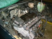
Make sure the bonnet is securely propped open (it'll hurt if it drops on your head), remove the battery and set it aside.
Set the handbrake and chock the rear wheels.
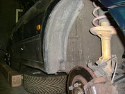
Break the tension on the front wheel nuts, jack up and support front of car on both sides with axle stands under the rear extensions of the sub-frame and remove the wheels.
Note: Make sure now that you will have enough ground clearance to remove the gearbox from under the car. If you use a trolley jack under it like I did you will need a bit more room!
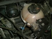
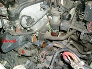
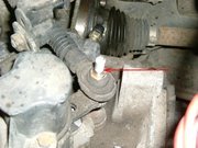
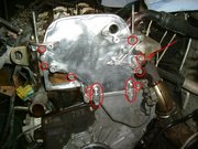
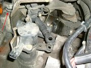
Drain the coolant. If the engine is hot, let it cool down first. I collected it in a large drip tray because it tends to get everywhere; it should be disposed of in an environmentally friendly manner, ie NOT poured down the domestic drains. Remove the header tank top cap
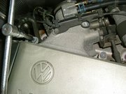
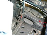
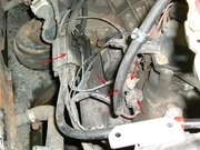
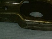
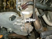
and open the drain tap on the engine cross feed pipe and/or disconnect the bottom hose. The drain tap is a knurled cap with a screwdriver slot in its centre; it is located to the side of the alternator and is difficult to get at
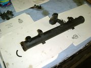
Damaged coolant crossfeed pipe
. I drained mine at the bottom hose at this stage, which is also not readily accessible from above but slightly easier to get at from below, and drained the block later on.
Remove the plug leads; you will need Special Tool No T10029.

Removing spark plug leads with tool T10029
Don't try to pull the leads out by hand as it is more than likely that the lead will pull out of the cap which will stay attached to the plug. This means you can't get the plugs out – well not without a lot of grief anyhow!
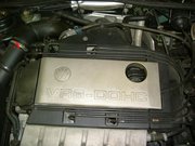
Unscrew the 4 x M8 spline drive bolts to remove the 4 plastic covers and 3 x M8 spline drive bolts to remove the centre plate from the top of the engine. The front plate slides to the passenger side and unclips from the head mounted bolts.
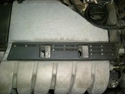
Front plug lead guide loosened
,037
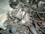
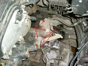
Detach the two coolant pipes from the throttle body. A
Loosen the clamp B and detach the large hose from the throttle body.
Disconnect the 2 plugs C (this is a blank) and D, undo the cable clips E and put the wiring aside.
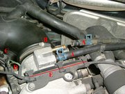
Throttle body heating pipe removal
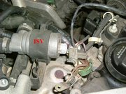
Disconnect the wiring connector from the ISV
, separate from the air inlet and remove it with its pipe-work.
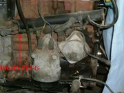
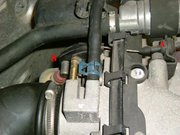
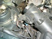
Detach the pressure regulator and vacuum pipes.

Throttle body inlet pressure regulator
As you can see from the oil round here the pressure regulator commonly fails; see parts list for details.
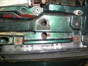
To disconnect the throttle cable, pull the rubber grommet from the ‘U' bracket A and unhook the cable end nipple from under the throttle quadrant, B
Detach the coolant hose A vacuum pipe B and wiring connector C from the inlet manifold.
Inlet manifold vacuum pipe/wiring removal
Disconnect the wiring connectors from the coil pack A and cam position sensor B (watch out that the little moisture seals don't fall out and get lost), undo the 4 x M5 hex drive screws and remove the coil pack.
Remove the top and bottom radiator hoses.
Undo the M6 hex drive screw and disconnect the earth lead bracket from the rear of the inlet manifold.

Inlet manifold earth connection
Remove the 9 x M6 hex drive bolts from the front of the inlet manifold and remove it. (Not a lot of room with the slam panel in situ but can be done fairly easily) Remove the gasket and keep it safe.
Disconnect the auxiliary water pump wiring connector.
Aux pump wiring connector
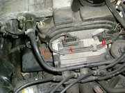
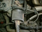
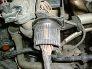
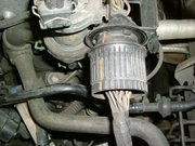
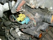
Disconnect the engine multi-way plug and the wiring connector plug from the back of the gearbox.
Note: Grab the centre bit of the multi-plug and twist it firmly anticlockwise and it will screw off; you can see the red marker line showing the locked, mid way and free positions.
Detach the heater hose from the bottom of the auxiliary water pump A and detach the other hose from the temperature sensor housing B and from the bottom of the header tank.
Detach the auxiliary water pump rubber mountings (mine were perished and broke so had to be replaced, see parts list) from the bracket and put it to one side, or remove the pump from the mountings instead.
Undo the 3 x 10mm bolts securing the mounting bracket, being careful not to damage any of the wiring and place out of the way (I laid mine along the fuel rail with the injector wiring).
Optional. Loosen the air box clamp A
and detach the air pipe A and connector B
I took mine out as I was going to do the rear engine mount later.
To remove, unhook the 2 rubber securing rings A and lift out.
Note: Loop a length of string through the rubber rings, and pull them up to get them off the brackets.
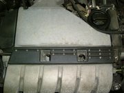
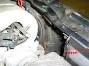
Undo the single Phillips screw and remove the plastic cover from behind the driver's side headlamp.
This shows the cover removed and the air box feed shroud which I also removed. It is held in with a Phillips screw A and 2 x 10mm plastic nuts B against the inner wing.
Unclip the fuel lines from the cam cover.
Remove the grille.
Remove both headlamps. Remove the two Philips screws on top of slam panel A and loosen the one through the hole in top of slam panel B pull the lamp forward and disconnect the plug.
Note: Experience now tells me that this would have been a good point to remove the bumper and slam panel as it gives greater access to remove the gearbox, and also allows for easy removal of the radiator. Stupidly I only did this later, but then decided to remove the radiator support panel and the cross-member and a bunch of other stuff and get it all shot-blasted and powder coated. See separate sections on how to remove them as individual tasks, and some pix of them in before and after condition.
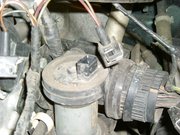
Remove the coolant temperature sensors shroud. It's a tight fit and pulls off sideways towards the gearbox. Disconnect the 3 coloured connector plugs noting their positions for later.
Undo the 17mm nut to free the PAS hose support bracket from the bottom of the gearbox.
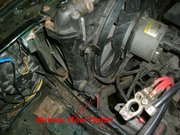
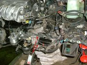
Disconnect the starter solenoid wiring noting positions for later replacement, 1 plug and 2 +ve wires (to battery +ve and alternator feed).
Disconnect and fold back the wiring connectors (and the cable tidy) from top of front engine mounting and starter solenoid.
Undo the 2 x 16mm bolts and remove the starter motor. (This is a shot of my rebuild, where you can see I have attached the battery –ve cable with the top fixing bolt)
Support the engine under the sump to just take the weight off the front mounting. I used a trolley jack with a piece of wood to spread the load running fore and aft in the ‘sump step' next to the gearbox.
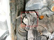
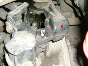
Undo the 16mm engine front mounting bolt A, undo the 17mm bolt B and remove the front engine mounting top bracket.
Front engine mounting bracket
To remove the upper part of the front mounting, undo the M8 hex head screw A from the underside of the cross-member. To remove the lower part of the mounting, undo the 3 x 13mm nuts securing the cap to the underside of the cross-member.

Front engine mounting lower
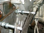
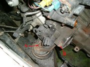
Disconnect the top cable by lifting the plastic clip and sliding the cable nose off the actuator pin.
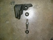
Disconnect the lower cable by removing the top nut A and removing the balance weight B
Gear change balance weight
Unscrew the pillar bolt
and disconnect the cable
Bottom gear cable linkage
Note how the washer and lower non-captive nut mate with the bracket. The parts
Undo the 3 x 13mm bolts and remove the gear change cable bracket from the bell-housing (the clutch slave cylinder pipe is clipped to it), note the rubber/steel combination washers.
Remove the 2 x 13mm clutch slave cylinder bolts remove the cable support bracket and tie the cylinder up out the way (do NOT disconnect its hydraulic line).
Replace the bolt next to the bell-housing inspection plug to hold the release arm in position. (I don't really think this is essential but VW recommend it. I put all 3 bolts back in as a good place to store them)
Clutch slave cyl position and gear linkage removed with bolts replaced
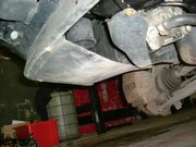
If not done already, undo the Phillips screws and remove the two plastic splash guards (one each side) from the outer underside of the bumper.
If not done already, undo the mix of Phillips and 8mm hex head screws and remove the plastic inner liners from both wings.
If not done already, remove the remaining plastic panel from the driver's wheel arch (Philips and hex again).

Driver's wheel arch panel
Remove the 6 x M8 spline (12) drive bolts from both drive shaft to final drive couplings. Tie the driver's side shaft up so as to take any angle load off the outer CV joint.
Optional: I removed the passenger side hub to give me more room to remove the gearbox.
Undo the 2 x 13mm bolts & 15mm lock nuts and suspend the calliper body from the strut (don't allow it to hang by its brake line).
Undo the 19mm nut, separate the taper joint and disconnect the steering arm. Note: if you haven't got a ball joint splitter use two hammers to simultaneously hit both sides of the steering arm. Do NOT hit the end of the taper joint because you will damage it. You don't need to give it the Desperate Dan treatment, just set up a steady rhythm and the vibrations will free it off.
Undo the 3 x 13mm bolts and remove the triangle bracket from the wishbone. The hub can then be pulled free from the wishbone. (Alternatively, remove the 19mm lower ball joint nut and separate the wishbone from the hub carrier that way but personally I think that's a much harder option).
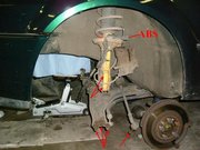
Uncouple the ABS wiring connector and separate the cable bracket from the strut.
Mark the relative positions of strut and hub arm (this so your camber setting won't be too far out when you rebuild it) and remove the 2 x 18mm nuts and bolts securing the hub to the strut and put the hub to one side.
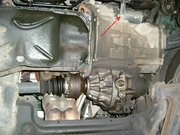
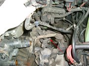
Just take the weight of the gearbox using a small trolley jack and undo the 5 x 13mm and 1 x 16mm bolts to remove the bracket and gearbox to sub-frame mounting. (Just look at my dead mounting leaking all over the place)
Remove the 2 x 10mm bolts holding the bell-housing cover plate. (All this oil from dead oil cooler seals)
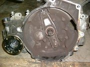
Remove the 4 x 19mm gearbox bell-housing to engine bolts (one at rear just above the final drive coupling; two on top under the timing chain cover; one just behind the starter housing – you'll have to look for them as I didn't photograph them) and pull the gearbox off the flywheel. This is a bit tricky as you will need to support the weight of the gearbox (trolley jack) and twist the box forwards so that the final drive couplings clear the sub-frame as you pull it off the shaft.
Note: By the time I replaced it I'd got sensible and bought a wing-top support beam to suspend it from. Not essential but by golly it made it really easy to refit the box.
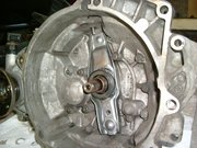
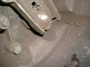
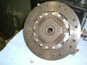
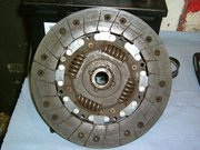
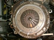
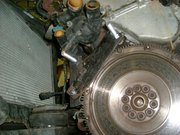
Here you can see the state of my clutch when it came off. Inside the bell-housing
; Marks on the pressure plate cover caused by the release arm having fractured and bent (caused an awful chattering)
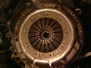
Pressure plate cover - scored
; End of the release arm worn away
; Fracture line on the release arm (it was broken on both sides)
; Friction plate almost worn smooth
; Heat marks on pressure plate and flywheel which polished off nicely with some fine wet and dry and a little patience

Heat marked pressure plate
.
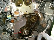
Timing Chains & Tensioners
Now at last we start getting a bit nearer to the timing chains and tensioners.
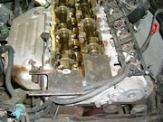
Remove the spark plugs using a 1ft extension bar and 14mm plug socket and loosely plug the holes with bits or rag or similar so you don't drop anything down there.
Undo the 8 x 10mm bolts and 2 nuts and remove the cam cover (some engines have a slightly different set up).
Using a 27mm socket rotate the crankshaft pulley clockwise to align the timing notch in the rear part of the pulley with the timing mark on the engine end cover.
Note: If you overrun it by more than a few degrees then I recommend you keep going all the way round again.
Crankshaft pulley aligned on timing mark
This will set the engine to one of the No1 cylinder TDC positions.
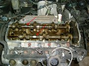
Now look at the slots machined in the end of the camshafts, they will be in the horizontal position. Because the cams rotate one complete revolution for every two complete revolutions of the crankshaft, they may be at either the No1 cylinder firing position or
180 degrees away ie ‘upside down'. To identify the correct position the slots are cut off centre, so you will see a small segment (upper) and a large segment (lower) when the cams are in the No1 firing TDC position. The end lobe on the rear cam is up and slightly aback, and the end lobe on the front cam is pointing straight down.
VW use a special plastic tool to ‘lock' the cams in this position while working on the timing chains. I used a couple of pieces of 3mm metal plate which I think are better as they are more robust; but it's up to you, it's not rocket science. If the cams are ‘upside down' simply turn the crankshaft pulley through another clockwise rotation until the timing marks are aligned again. Do not lock the cams at this stage.
Looking at the engine from the gearbox end the front cam is pulled anticlockwise by the duplex chain with the rear cam following, so there will be little/no slack between them.
The timing chains are encased by two covers, upper and lower, and which are bolted together. In order to remove the lower cover the flywheel must first be removed.
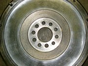
Undo the 6 x 8mm ‘star' bolts and remove the pressure plate cover and the friction plate noting which way round the friction plate fits for later.
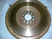
The flywheel is held on with 10 x M8 spline drive bolts and new ones should be fitted when it is finally replaced. Considerable turning force will be required to undo and tighten them so for your safety the engine MUST be ‘locked' to prevent it rotating.
Note: Several methods are known to be employed, including:
Use of a suitable tool (typically, a large screwdriver) held in the starter ring teeth and against the engine block;
An assistant using a 27 mm socket/spanner to hold the crankshaft pulley bolt;
Use of a bespoke flywheel locking tool;
I dislike the ‘screwdriver' approach because there is a very high likelihood of it slipping and risk of personal injury in the event.
I also dislike holding the crankshaft pulley because, although a safer option than the ‘screwdriver', there is a chance (remote I admit) that it, rather than the flywheel bolt, will unscrew.
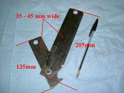
I would therefore only recommend the third option, use of a bespoke flywheel locking tool. See the Tools Required section for details of how I fabricated mine.
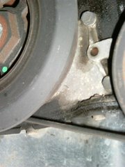
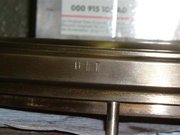
Note that there is also a timing mark on the edge of the flywheel which should be in alignment with a mark on the lower chain cover.

Flywheel and chain cover timing marks
Lock the flywheel and remove the 10 x M8 spline drive fixing bolts.
Remove the locking tool, and the flywheel from the crankshaft, this has a slight taper fit so it may need to worked side to side to loosen it.
Recheck that the crankshaft pulley timing marks are still aligned. If not, the crankshaft pulley should be turned clockwise until correct TDC alignment is achieved, with the cam slots exactly horizontal and the small end segment uppermost.
Now fit the cam locking plates. Do NOT remove them until work on the timing chains has been completed and the top chain cover and tensioner bolt have been refitted.
Remove the 27mm upper chain tensioner bolt.
Top tensioner bolt removal
Remove the 8 x M5 hex drive bolts from round the edges of the upper chain cover and remove the 2 x M6 hex drive ‘upright' bolts where the covers join.
Note: Very carefully work the top cover away from the engine and its 2 locating pins. Be careful because the head gasket extends around the timing chains and is clamped between the top and bottom chain covers.
Here you can see the intermediate sprocket and its keyway down inside the lower cover.
Intermediate sprocket keyway
Remove the 19 x 10mm bolts from around the lower chain cover (note, 1long at top right and 3 upwards through the sump lip) and remove it, again taking care not to damage the head gasket. It may need rocking to free the oil seal from the crankshaft nose.
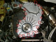
Lower chain cover removal
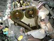
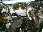
With the covers removed you can see the whole chain set up and now exposed section of the head gasket. Actually, this is a pic of when it went back together as my laptop was down and my camera card was full at the time so you can see the new type top tensioner here.
Chain Stripping
Again I've used some of my rebuild pix to show you more clearly how it all works, and assumes the chains guides and tensioners are all being replaced.
It's worth repeating here, take care at all times not to damage the head gasket – doing so will seriously spoil your day, so take your time and go steady.
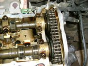
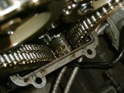
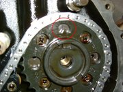
Have a good look at the Intermediate Sprocket. It is made up of two interlocking gear wheels, one simplex (inner) and one duplex (outer). The simplex gear has a series of holes drilled around its circumference through which the (two) fixed timing marks on the back plate behind it are viewed. At this point it is difficult to see both these timing marks because the top one is obscured by the duplex chain.
No problemo, this will all be clear to you as we progress.
To remove the chains you first need to undo the 15mm intermediate sprocket bolt, and what you can also see here through the bottom hole in the rear sprocket is the lower timing mark on the back-plate.
Intermediatesprocket bolt
The sprocket bolt is tight (100Nm) so you need to lock the engine against rotation again so temporarily refit the flywheel with a couple of the old bolts and refit the locking tool.
Note: The flywheel bolt holes are drilled offset so the flywheel only fits in one position on the crankshaft, remember the timing mark on the edge that we saw earlier – fits at about the 1 o'clock position.
Flywheel bolt holes - offset
Flywheel edge timing mark
Undo the sprocket bolt, remove the engine lock and remove the flywheel.
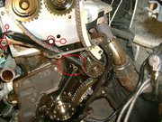
To provide a bit of slack in the duplex chain you can undo the 2 x 13mm bolts holding the upper guide rail and allow the rail to pivot forwards on its locating pin.
The intermediate sprocket is made up of two parts and you can now carefully (watch the head gasket) pull the outer part away from the rear part and remove it from the chain.

Intermediate sprocket separation
Intermediate sprocket outer removed
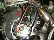
You can now remove the duplex chain from the cam sprockets and slide the guide rail from its locating pin to remove it. The top tensioner will then swing down on its pivot pin below the head gasket and can also be removed.
Top tensioner pad lowered
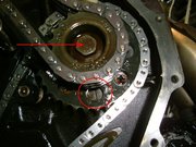
Now you can clearly see the intermediate sprocket timing mark, it looks like a small gear tooth, aligned with the top timing mark on the back-plate.
Intermediate sprocket timing mark
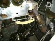
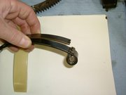
Undo the 2 x M8 hex head bolts and remove the lower tensioner.
Note: Because it is under pressure it will spring open when removed. The first pic shows the new one with its spring retaining clip in place.
Pull the rear section of the intermediate sprocket away from the back-plate and remove the chain, together with the lower guide rail, from the crankshaft teeth.
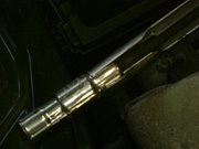
You can now see the spindle on which the intermediate sprocket runs, and the ‘flat' with which it engages.
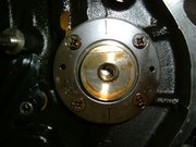
Intermediate sprocket spindle
With the two parts of the sprocket removed you can clearly see how they lock together.
You will also see that the intermediate sprocket spindle is now free to turn, but no need to be concerned because all it does is transfer drive to the oil pump and it will be re-positioned when the sprocket is replaced later. For interest, you can also now see the TDC timing mark on the flywheel end of the crankshaft. One of the (chain) teeth is chamfered to make it unique and it is aligned with the crankshaft main end-cap joint.
Now is a good time to clean any sealing compound residue from the engine block and chain covers in preparation for refitting later. You might also find tiny bits of crumbled tensioner material in the area as a result of top tensioner wear; just clear it away, its not a problem.
Here you can see the scoring on my old tensioners. The Lower one wasn't too bad
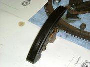
Lower tensioner pad scoring
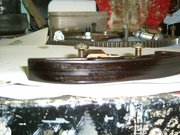
Lower tensioner pad scoring
. The Upper one was on its last legs and one end had fractured at the rivets so I had just caught it in time
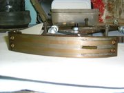
Top tensioner pad scoring
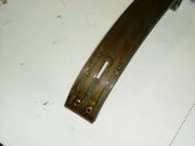
Top tensioner pad scoring
Top tensioner pad last legs
.
Continue to part 2