Gauge pod fitting guide
From THE Corrado Forum Knowledge Base
To Fit the gauge pod and get it working correctly you will also require a T-piece and single pole 0-10 bar sender or for the method used here a 0-10 bar dual pole sender (available from Merlin Motorsport based at Castle Combe).
On the rear of the gauge are 4 terminals marked as follows from top to bottom and connect as shown:
     GDruck          To Sender
     KL15+12v        To Switched Live
     KL31            To Earth
     KL58+BEL        To Illumination
Contents |
Electrical Parts Needed
Buy 4 crimp terminals to fit the connections on the gauge (These are small like the ones used for speakers), 1 blue piggy-back crimp terminals, 2 blue ring crimp terminals and 1 blue female and 1 male crimp terminals, a scotchlok connector and some suitable wire (1.5mm should be ok). Heatshrink can be used if required to insulate and tidy things up.
Connecting Sender
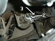
In the picture remove the connector with the blue wire which is the right hand one as you look from the front of the engine, then remove the sender and screw the 0-10 bar dual pole sender into the housing.
Connect the ring terminal on the wire which goes to the gauge to one terminal on the sender (No. 2 in the pic) and then connect the ring terminal on the 3" wire (No. 3 in the pic) to the other terminal on the sender, and the male crimp terminal to the original blue sender connector (No. 1 in the pic)
Connecting Switched Live to Glove Box Light

Connecting Earth
Crimp the correct size terminal for the gauge to a piece of wire and fit to the gauge. Remove the driver's side lower panel and the fusebox cover, then run the other end of this wire over to the fusebox. If you look above the fusebox to the right you should see the metal earth plate with several spare male spade terminals. Crimp a female terminal to the wire and push this onto one of these spare terminals.
Connecting illumination
Crimp the correct size terminal for the gauge to a piece of wire and fit to the gauge. Remove the ashtray and cigarette lighter trim carefully and then use the scotchlok connector to splice the other end of the wire into the blue/grey wire in the cigarette lighter loom.
Finally
Recheck all connections, test operation of guage pod then fit the pod into the binnacle.