VR6 Clutch and Timing Chains Replacement Part 2
From THE Corrado Forum Knowledge Base
2CC's CLUTCH AND TIMING CHAIN REPLACEMENT ON VR6 M151 GRP
This is continued from Part 1
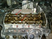
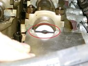
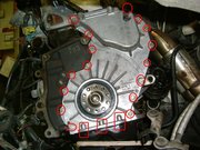
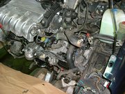
Chain Replacement This bit is critical for correct timing. Recheck the crankshaft and cams are at TDC and the cam locks are in place. It may now be some days later after you've messed about doing other stuff, and you can never check this too many times! Decide which of the back plate timing marks you are going to use. Trust me here, it really does not matter which one. Temporarily engage the rear section of the intermediate sprocket with the spindle and then turn it until the timing marks are aligned in the position you have chosen (ie top or bottom). Remove the sprocket without turning it, the spindle will stay in position.
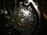

Slot the simplex chain into the new lower guide rail and slide it onto its mounting pins whilst simultaneously engaging the chain on to the crankshaft teeth. Engage the rear sprocket in the chain and, keeping the front of the chain taut, ‘walk' the sprocket round on the chain tooth by tooth (if necessary) until the sprocket engages on the spindle. Your chosen timing marks should now be exactly aligned. I have positioned mine with the marks at the bottom. This is because you can then still see them when the duplex chain is fitted – it's your choice. This is what it should look like; no slack round the crank or the sprocket at the front.
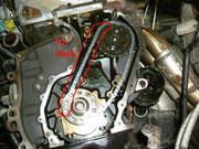
Now fit the new lower tensioner and screw in the bolts finger tight for the moment - I fitted new ones as they can get a bit chewed on removal. Remove the wire clip keeping it compressed. (If this comes out before you get it fitted the tensioner can be re-closed by depressing the ratchet with a small screwdriver in the hole indicated and squeezing it together).

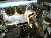

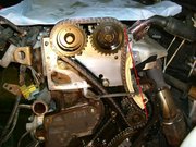
Rotate the crank another turn to get it back to true TDC. The cam slots should be exactly horizontal and the locks able to fit. If not you have somehow managed to set the timing one or more teeth out and will have to recheck the preceding chain fitting procedures. If all is OK you can relax, feel chuffed with yourself, and go and have a brew.
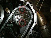
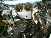
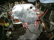
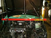
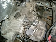
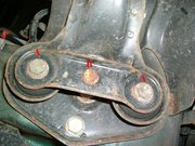
Now you are suitably refreshed, refit the cam locks, remove the tensioner bolt and the top chain cover again. Tighten the lower tensioner bolts to 10 Nm. Remove the lower bolt from the top guide rail (there is minimal clearance with the chain so a thin walled socket is handy here), apply a little loctite to the threads and replace it. Tighten both the guide rail bolts to 20 Nm. Temporarily fit the flywheel again with a couple of the old bolts and lock the engine against rotation. Tighten the intermediate sprocket bolt to 100Nm. Remove the engine lock and flywheel. Note: By locking the crankshaft the tightening load is taken directly by the front part of the lower chain, this is OK. Do NOT try to use the cam locks to hold the engine as turning the bolt will put load on the un-tensioned rear of the duplex chain, which is NOT OK. This will produce some backward rotation of the intermediate spindle (and pull the crankshaft with it) before the rear of the duplex chain tightens, and you can see from pic
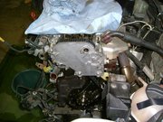
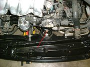
Now it's time to refit the lower chain cover. I fitted a new oil seal to mine though unfortunately didn't have the camera available, but changing it is easy. First look to see how the seal is seated in the cover, then supporting the cover on a couple of bits of wood knock it out using a flat punch (or similar) and hammer working round it a bit at a time. Take care not to damage the mating surface of the cover. Clean the cover and lightly oil the mating surface. Position the new seal making sure its lip has not been trapped then, using a piece of wood that spans the seal, tap it gently into place. The new seal is supplied with a cunning plastic surround that expands the lip so that it does not foul the crankshaft nose when refitting the cover to the engine; it works really well. Apply sealing compound sparingly to the mating surfaces of the cover and refit it to the engine, taking care not to damage the head gasket. Note: Do NOT apply sealant to the top edge which mates with the head gasket; a light smear of oil is appropriate. Tighten all the cover bolts to 10 Nm.

Refit the tensioner bolt and tighten it to 30Nm.
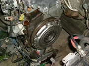
Refit the flywheel, the TDC edge marking aligned with the timing mark on the chain cover, and secure it with the engine lock. Working from side to side, tighten the new bolts to 70Nm + 90 degrees (you will need an angle measurement tool for this). Remove the engine lock.

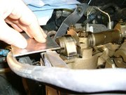
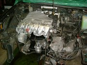
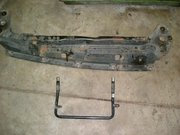
Refit Gearbox Either eat your spinach or rig up a support frame if you have one. This cost me £58.69 from Machine Mart but my back isn't what it used to be so I consider it money very well spent as it made the job really very easy. (I am happy to loan it out)


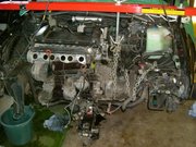

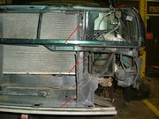
Now it's time to refit all the loose bits that you have either painstakingly cleaned in preparation, or left in a heap in the corner. So in true Haynes fashion, refitting is a reversal of the removal procedure but will vary depending on what you removed in the first place. Because I decided to remove the front from the car during the job, my rebuild is in a different order to the strip down, but in general it will include the following:
If you removed it, refit the passengers' side hub, steering tie rod, ABS connector and the brake calliper. Refit the drive shafts to the final drive couplings and tighten the bolts to 45Nm. Refit the clutch slave cylinder tightening the bolts to 25Nm (don't forget the cable support bracket like I did here).
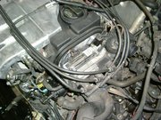
Refit the air-guide and air-box, the air inlet pipe to the throttle body and ISV.


If you removed them, refit the slam panel and the radiator top mountings tightening to 10Nm.

If you removed them, refit the shoulder bolts to secure the chin spoiler to the bracing strip and radiator support frame tightening to 2Nm. Refit the inner wing panels (the small panel by the crankshaft pulley must be fitted first) and corner shrouds tightening the screws to 1.5Nm. Refit and reconnect the headlamps and replace the plastic back panel on the driver's side. Refit the grille. Put the wheels back on, put her back on the floor and fully tighten the wheel nuts (torque varies with wheels). Undo the hose from the top of the radiator and, with the header tank cap removed, use it as a funnel to refill the engine with new "G12 plus" coolant. Give the other hoses a squeeze to help expel any air in the system as it fills. When it overflows, reconnect the top hose to the radiator. Note: Don't fill it at the header tank initialy as that will often result in air being trapped in the system, but top up there later. This may cause: poor heater; unusual temperature readouts; engine overheating. Refit the engine multi plug and the wiring connector to the top of the gearbox (if you forget this you will have no speedometer, mpg, miles run or mph readouts). Refit and reconnect the battery and re-code and disarm the alarm. Turn the key and love that sound as she comes to life again. While she warms up, re-enter your radio code. Top up the coolant at the header tank and fit the cap. Check for leaks. If you took the hub off you will need to have the camber angle and tracking re-set. Now go out and enjoy yourself after a job well done.
Bumper Removal You don't have to remove the indicator or fog lamps do this but I thought it might be useful to say how. Stick the end of a flat blade screwdriver between the indicator and fog lenses and gently lever the indicator lamp forwards; once its popped free you can then pull the outer end free from its fixing point. This car has the later style bumper where the mounting panel for both lamps is held in with 4 self tapping screws


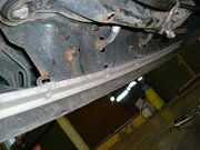
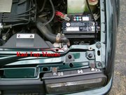
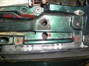
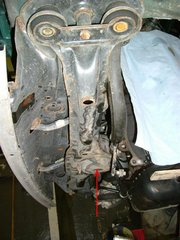
Remove the 4 x 17mm securing bolts, two on each side A, from underside of bumper. Do NOT remove the two smaller bolts, one each side B, which are situated between them; these secure the front cross-member which supports the engine.

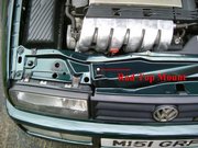
Slam Panel Removal Remove the headlamps and grille. Remove the two Philips screws on top of the slam panel A and loosen the one through the hole in top of slam panel B pull the lamp forward and disconnect the plug.

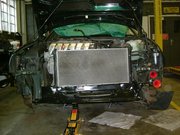
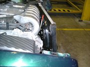
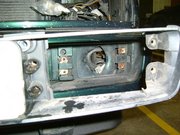
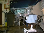
Radiator Support Panel Removal Remove the Bumper. Remove the Cross-member. Remove the Slam Panel. Drain the radiator and disconnect the hoses. Disconnect the radiator fan motor supply plug and temp sensor connector from lower left side. The radiator, complete with fans, motor and mounting frame, will now just be sitting on its support panel and can be lifted away (don't lose the rubber mounting washers from the end locating pins underneath). Cut the one time clips from the PS hoses where the link pipe passes through the panel (yeah, great design that, and buy some decent jubilee clips for later), but be careful not to damage the hoses or the link pipe. Catch the escaping fluid and dispose of it in an environmentally friendly manner. Note : Mine dropped less than half a litre so the reservoir was easy to top up later; I've heard some people's reservoir drained right out. When the system is re-sealed just re-fill the reservoir, run the engine and work the steering lock to lock till the level stays constant (it will drop as the system fills up) and the pump runs quietly (indicates all the air has been displaced). Top up the correct level and replace the cap. I ran mine while it was on the axle stands to take the load off. Remove the 1 x 17mm bolts from each side and the panel will fall off.

| VAG Part Name | Description | Part Number | Price ex VAT |
|---|---|---|---|
| Switch | ? | 05691908E | £7.63 |
| Connector | VR6 plug lead tool | T10029 | £16.80 |
| Coolant | engine coolant 1 1/2 ltr (2) | G012A8FM1 | £5.35 |
| Guide | upper timing chain guide rail | 21109513 | £7.59 |
| Guide | lower timing chain guide rail | 21109469 | £2.80 |
| Repair Kit | crank/lower timing case oil seal | 68198171 | £24.66 |
| Tensioner | Golf Mk4 top pad | 021109509E | £6.79 |
| Bolt | tensioner for Golf Mk4 top pad | 021109507B | £22.51 |
| Rub/Mount | engine-g/box mounting | 3A0199402 | £41.28 |
| Rubr Mount | engine-driver side mounting | 1H0199262K | £54.21 |
| Washer | temp sensor block water seal | 021121119A | £2.21 |
| O-Ring | temp sensor block water seal | N10139201 | £1.79 |
| Mounting | aux water pump rubber mounting | 066959209 | £2.53 |
| Mounting | aux water pump rubber mounting | 035959209E | £2.53 |
| Hex Bolt | dipstick tube fixing | N01021527 | £0.22 |
| Spring | clutch release arm retaining | 12141741 | £0.36 |
| Lever | clutch release arm | 02J141719B | £9.67 |
| Mounting | engine front mounting | 1H0199609K | £47.23 |
| Chain | lower timing chain - simplex | 021109465B | £29.27 |
| Seal Paste | casing sealant | AMV18800102 | £34.25 |
| Screw | g/box engine mounting fixing | N10241603 | £0.92 |
| Tensioner | lower timing chain tensioner | 21109467 | £19.93 |
| Screw | flywheel fixing bolts (10) | N90539801 | £0.82 |
| Ball Pin | clutch release arm pivot pin | 02A141777 | £2.26 |
| Chain | upper timing chain - duplex | 021109503A | £59.18 |
| 7307725 Clutch | clutch kit; p/plate, f/plate, release bearing | 021198141AX | £120.00 |
| Gasket | oil cooler seal | 38117070 | £2.17 |
| Bolt | lower timing chain tensioner fixing (2) | N9053501 | £0.14 |
| Gasket | oil filter housing seal | 021115446A | £5.41 |
| Bracket | radiator mounting | 535121267D | £2.57 |
| Bracket | radiator mounting | 535121267E | £2.57 |
| Spacer | radiator mounting (2) | 535121276C | £8.16 |
| Rubber Mtg | radiator mounting (2) | 535121275 | £2.48 |
| Hex Bolt | radiator mounting (2) | N01021527 | £0.23 |
| Bolt | front bumper fixing(4) | N90305901 | £1.81 |
| Screw | front crossmember fixing (2) | N0195461 | £0.42 |
| Bolt | chin spoiler fixing | N90433801 | £1.62 |
| Rubber Brg | front crossmember mounting (4) | 191199233 | £3.37 |
| Guide Ring | rad fan surrounds | 357121210 | £6.33 |
| Seal Paste | oil cooler seal | 038117070A | £2.57 |
| Oil | pas fluid | G002000 | £6.49 |
| Waterpipe | coolant transfer pipe | 021121050C | £14.51 |
| Washer | coolant transfer pipe o ring | 21906445 | £1.18 |
| Housing | eng temp sensor block | 021121117A | £22.30 |
| Seal | thermostat adaptor water seal | N90136802 | £2.16 |
| O Ring | transfer pipe outlet adaptor water seal | N10139201 | £1.49 |
| Adaptor | thermostat adaptor | 021121121A | £9.42 |
| Adaptor | transfer pipe outlet adaptor | 021121133D | £9.42 |
| Bolt | housing fixings | N0147035 | £0.45 |
| Washer | crankshaft position sensor oil seal | 21906445 | £1.18 |
| Pressure Regulator | inlet manifold pressure regulator – get this from Ford for a V6 Galaxy | Ford 7364573 | £18.41 |
You can also Download the parts list as a Word doc.
As you can see I rather went to town once I'd started, but got the VAT off as discount. Another £100 or so for powder coating brings it to a Total £749.65
General Tools Required
- Sockets, T-Bar, (Ratchet useful) 8 to 19mm, 27mm. A thin walled 13mm socket will be useful.
- Spanners, Ring & Open 8 to 19mm, 27mm
- 17mm hex drive (Gearbox plug)
- Hex and Spline drive Set (Sealey AK219 is a good one)
- Hose clamp pliers (Sealey VS166)
- Hammers
- Straight drift
- Screwdrivers
- Torque wrenches
- Angle Gauge (Sealey VS531)
- Jacks
- Axle stands
- Gearbox support frame (optional, Machine Mart, Clarke CEC300)
- Bits of wood
- Degreaser
- Cleaning Paper/Cloths
- Power drill, bits, files
- Wire brushes
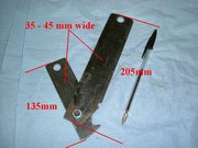
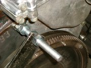
Engine Locking Tool
- 4mm thick steel bar cut and drilled to suit.
- 1 x 8mm nut & bolt.
- M12 studding bar cut to suit.
- 8 x M12 hex nuts.
I cut the steel bar to the lengths shown; these are not critical but work fine at these dims. Then I drilled 12mm clearance holes at the ends. I cut the studding bar to give two 130mm lengths and locked two nuts together on each to give 15mm of thread to screw in and lock to the engine block. I slid the shorter bar on to the front bolt, checked the engine was at TDC, and cut and filed the notch/tooth to give an accurate fit into the starter ring. Then I slid the longer bar onto the rear bolt and temporarily clamped the bars together, then removed them and drilled the pivot hole through them (still clamped). When assembled on the engine as shown and with the pivot bolt also tightened this completely locks the flywheel with no possibility of it moving.